
Have you ever wondered how to clean up a noisy audio signal or remove unwanted frequencies from your data? Designing a simple low-pass filter from scratch might just be the solution you’re looking for. Whether you’re an electronics enthusiast or a budding engineer, creating your own low-pass filter is a rewarding project that enhances your understanding of signal processing.
What Is a Low-Pass Filter?
A low-pass filter is a basic electronic circuit that passes signals with a frequency lower than a certain cutoff frequency and attenuates signals with frequencies higher than the cutoff frequency. It’s an essential tool in various applications, from audio processing to radio communications, where it helps in eliminating high-frequency noise and ensures signal integrity.
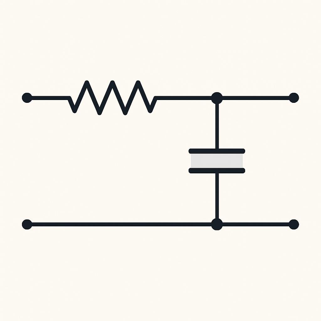
In its simplest form, a low-pass filter can be constructed using just a resistor and a capacitor. This configuration is known as an RC low-pass filter. The simplicity of the design makes it an excellent starting point for anyone interested in electronics.
How It Works
The key to understanding a low-pass filter lies in its frequency response. The cutoff frequency, denoted as fc, is the frequency at which the output signal power is reduced to half of the input signal power, which corresponds to a -3 dB point. For an RC low-pass filter, the cutoff frequency can be calculated using the formula:
fc = 1 / (2πRC)
Where:
- R is the resistance in ohms (Ω).
- C is the capacitance in farads (F).
The filter’s function is based on the principle that capacitors resist changes in voltage. At low frequencies, the capacitor charges and discharges slowly, allowing the signal to pass with little attenuation. At high frequencies, the capacitor’s impedance decreases, effectively shorting the signal to ground and attenuating it.
Step-by-Step Guide to Designing a Low-Pass Filter
Now that we have a basic understanding of how a low-pass filter works, let’s dive into designing one from scratch. Follow these steps to create your own RC low-pass filter:
Step 1: Define Your Requirements
Before you start building, it’s crucial to define the specifications of your filter. Ask yourself the following questions:
- What is the desired cutoff frequency?
- What is the input signal frequency range?
- What are the acceptable levels of signal attenuation?
Having clear requirements will guide your component selection and overall design.
Step 2: Select Components
With your requirements in hand, it’s time to select the resistor and capacitor values. For example, if you want a cutoff frequency of 1 kHz and have a capacitor of 100 nF, you can calculate the required resistor value using the rearranged cutoff frequency formula:
R = 1 / (2πfcC)
Plugging in the values:
R = 1 / (2π * 1000 * 100 x 10-9) ≈ 1.59 kΩ
Choose the closest standard resistor value, which is 1.6 kΩ.
Step 3: Build the Circuit
Once you’ve selected your components, it’s time to build the circuit. Here’s a simple setup:
- Connect the resistor (R) to the input signal source.
- Connect one end of the capacitor (C) to the output side of the resistor.
- Ground the other end of the capacitor.
- The output is taken across the capacitor.
This configuration will allow low-frequency signals to pass through while attenuating higher frequencies.
Step 4: Test and Adjust
After assembling the filter, it’s essential to test its performance. Use an oscilloscope or a signal analyzer to observe the output signal. If the cutoff frequency or attenuation isn’t as expected, adjust the resistor or capacitor values accordingly. Remember that component tolerances can affect the actual performance, so a bit of tweaking might be necessary.
Common Mistakes to Avoid
While designing a low-pass filter is straightforward, there are common pitfalls to watch out for:
- Incorrect Component Values: Double-check your calculations to ensure you’re using the correct resistor and capacitor values.
- Ignoring Parasitics: Real-world components have parasitic resistances and capacitances that can affect performance, especially at high frequencies.
- Poor Grounding: A solid ground connection is crucial for filter performance. Ensure all grounds are connected properly.
- Overlooking Noise Sources: External noise can affect your filter. Consider using shielded cables or enclosures if necessary.
Real-World Examples
Low-pass filters are ubiquitous in electronic devices. Here are a few real-world applications:
Audio Systems
In audio applications, low-pass filters are used to separate bass frequencies from higher frequencies, ensuring that speakers and subwoofers handle the appropriate frequency range.
Data Acquisition Systems
Low-pass filters are used in data acquisition systems to remove high-frequency noise from sensor signals, providing cleaner data for analysis.
Radio Communications
In radio transmitters and receivers, low-pass filters help to eliminate unwanted harmonics and spurious emissions, ensuring compliance with transmission regulations.
Final Thoughts
Designing a simple low-pass filter from scratch is a fantastic way to deepen your understanding of electronics and signal processing. By following the steps outlined in this guide, you’ll be able to create a functional filter tailored to your specific needs. Remember, practice and experimentation are key—don’t be afraid to tweak your design and learn from the process. Whether you’re working on a hobby project or a professional application, mastering the art of filtering will greatly enhance your engineering toolkit. Happy filtering!