
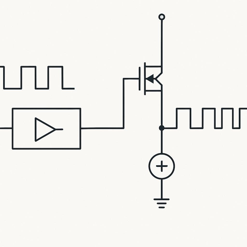
Imagine being able to control the brightness of a light bulb, the speed of a motor, or the volume of a speaker with high precision and efficiency. This is essentially what Pulse Width Modulation (PWM) allows us to do. It’s a versatile technique used in a variety of electronics applications, from simple LED dimming to complex motor control in industrial systems. Let’s dive into the world of PWM and explore its workings, applications, and how you can use it in your own projects.
What Is PWM (Pulse Width Modulation)?
PWM, or Pulse Width Modulation, is a method used to encode a message into a pulsing signal. It is a technique for getting analog results with digital means. PWM works by switching the power supply on and off at a high frequency. By varying the width of the “on” pulses, we can simulate a range of power outputs between fully on and fully off. This is particularly useful in applications where we want to control the power delivered to a device without the inefficiencies and heat generation associated with linear regulation techniques.
How It Works
The basic principle of PWM is pretty straightforward: you have a signal that switches between on and off. The amount of time that the signal is on versus the time it is off is known as the duty cycle, usually expressed as a percentage. A 100% duty cycle means the signal is always on, while a 0% duty cycle means the signal is always off.
- Duty Cycle: This is the ratio of the “on” time to the total period of the signal. For example, a 50% duty cycle means the signal is on for half the time and off for the other half.
- Frequency: This is how fast the PWM signal completes one cycle of on and off states. Higher frequencies mean more cycles per second.
- Resolution: This refers to the smallest change in duty cycle that can be controlled, often limited by the microcontroller’s capabilities.
Step-by-Step Guide to Implementing PWM
Whether you’re a hobbyist or a professional engineer, understanding PWM can open up a world of possibilities in your projects. Let’s walk through a simple example of how to implement PWM to control the brightness of an LED using a microcontroller like an Arduino.
- Set Up Your Hardware: Connect an LED to one of the PWM-capable pins on your microcontroller. Make sure to include a current-limiting resistor to prevent damage to the LED.
- Write the Code: Use an integrated development environment (IDE) like Arduino IDE to write a simple program. You’ll need to use functions that set the PWM value for the pin connected to your LED.
- Upload the Code: Connect your microcontroller to your computer and upload the code. This will start the PWM signal and adjust the brightness of the LED based on your code.
- Test and Adjust: Experiment with different duty cycles to see how the brightness changes. This will give you a better understanding of how PWM affects power output.
Common Mistakes to Avoid
While PWM is a powerful tool, there are a few common pitfalls to watch out for:
- Choosing the Wrong Frequency: Different applications require different PWM frequencies. For instance, LED dimming typically uses lower frequencies, while motor control might require higher frequencies to prevent audible noise.
- Ignoring Resolution: Make sure your microcontroller has enough resolution for your application. A low-resolution PWM signal might not provide the precision you need.
- Overheating Components: If you’re controlling high-power devices, ensure your components can handle the current and heat generated by rapid switching.
- Not Using Filtering: PWM signals can introduce noise into your system. Use filtering techniques where necessary to ensure stable operation.
Real-World Examples
PWM is used in countless applications across various industries. Here are a few real-world examples:
- LED Dimming: PWM allows for smooth and efficient control of LED brightness in everything from household lighting to high-end displays.
- Motor Speed Control: In electric vehicles and industrial equipment, PWM is used to control the speed and torque of motors without excessive power loss.
- Audio Amplifiers: PWM signals can be used in Class-D audio amplifiers to efficiently control the power delivered to speakers.
- Power Supplies: Many switched-mode power supplies use PWM to regulate output voltage and current, providing efficient power conversion.
Final Thoughts
PWM is a versatile and efficient technique that bridges the gap between digital control and analog output. Whether you’re dimming an LED, controlling a motor, or designing a sophisticated power supply, understanding PWM can significantly enhance your capability to manage power delivery in your projects. By mastering the principles of duty cycle, frequency, and resolution, you can unlock new levels of control and efficiency in your electronic designs. Embrace the potential of PWM, and you’ll find it a powerful ally in both simple and complex applications.